Land Surveyors and SG staff can capture coordinates data and clip maps directly from PDF content to generate the layers and shape files needed for lodgements, without doing all the capturing manually.
From PDFs, this module captures Coordinates into a table & enables Geo-referencing. Here's how.
LODGEMENTS MODULE
Video 1
Introduction to Projects and Submissions
Video 2
Capturing boundaries and beacons, Main Figure data and Erven areas from the PDF Text files(s)
Video 3
Georeferencing and Cropping (Clipping) a PDF Page
Video 4
Aligning Street Blocks to the Main Figure's Boundaries
Video 5
Aligning Erven (Land Parcel) Boundaries with Block Boundaries
Video 6
Generating Inner Erven Lines - for Back-to-back Land Parcels (Shortened version)
Video 7 ?
- Video-1
- Sign in
- Create a project (or Open an Existing Project}
- Add a Submission
- Video-2
- Capture Coordinates go to
- Type: "mainBoundary"
- Type: "mainCoordinate"
- Type: BlockCorner
- Type: SurveyMarks (not covered in video)
- Type: ErfArea
- Capture Coordinates go to
- Video-3
- Video-4
- Aligning Street Block Points to corresponding MainFigure go to
- Video-5
- Aligning Erf Boundaries to the above Street Block Boundaries go to
- Aligning Erf Boundaries to the above Street Block Boundaries go to
- Video-6
- Creating Inner Erf Lines (Splitter lines for back-to-back land parcels) go to
- Video 7 ?
- Automated Inner lines process go to
- Video 8 ?
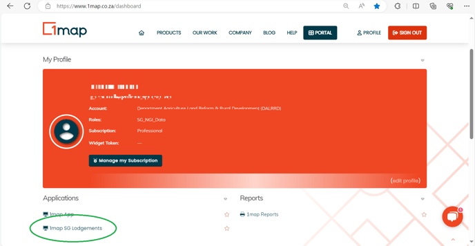
Sign in
sign in to 1map and, from your dashboard, go to the SG Lodgements app:
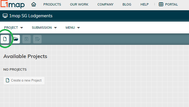
Create a project
Click on the icon and enter a Project Name for it.
or Open an Existing Project
![]() from those listed.
from those listed.
Add a Submission
Click on Submissions, and then on the green + icon.
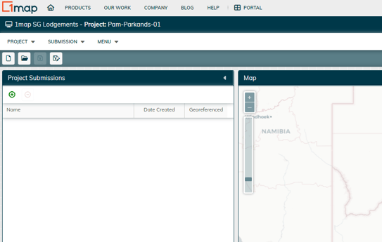
A New Submission window is displayed.
Select the Surveyor name from the dropdown,
Enter a date (use the calendar button)
Add a meaningful reference as this is the name under which file will be saved,
Enter a description for future reference,
Browse to and select the PDF file you have the image in that you wish to process here. The PDF must be a single PDF with all the pages concatenated into a multi-page PDF. This is not a scanned-in PDF, it must have been generated from an application such as a CAD app.
Then Save.
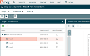
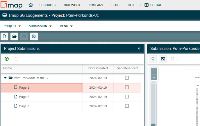
The pages are uploaded and are listed in the Project Submissions panel.
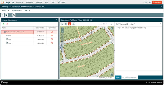
Click on the first icon in the second panel (this displays Submission: and the name of project submission). This opens the Capture Coordinates panel to the right .
![]()
Capture Coordinates
In the Project Submissions panel, click on the first page within the folder, which typically holds the coordinates you are going to copy from.
You can now collapse the Project Submissions (by clicking on the heading) to have maximum space for the image on the left and the Capture Coordinates on the right.
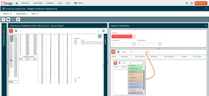
Now click on the Type: dropdown and choose 'mainBoundary"
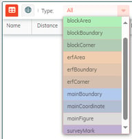
Type: "mainBoundary"
You will be capturing the following in this order:
- System (Projection) (e.g. WG19) choose from the dropdown. Look on the image under Main Figure, Co-ordinates, System for this information.
- Constant X (or Y) - found in Main Figure/Co-ordinates under the X or Y column. This is the offset from the equator needed to adjust the distances listed in the General Plan image.
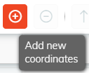
- First, click on the + icon:

- Now you will use the mouse to inscribe a rectangle around the column of information under Main Figure, left columns in the image (headings are Sides, Metres, Angles of direction).
- Hold down Ctl-key and click and drag the left mouse to draw a rectangle around the entries listed, then release. The Blocks Detected window appears showing the data that has been recognised from the image.
- Sight check what appears in the Blocks Detected [mainBoundary] window, and make corrections if necessary. (you can drag and enlarge this window to see more entries at one time). Once you are happy, click on Add/Update. Now click on the + button next to the Type: mainBoundary entry that has now appeared (with a count of the entries you just added). All entries will now appear and to check on an entry, click on it in the Capture Coordinates panel. It will highlight the corresponding item in the image on the left, and vice versa. Once you are satisfied that the fields are identical, save the Project:

- First, click on the + icon:
-
Type: "mainCoordinate".
- Click on the Type: dropdown and choose mainCoordinate.
- Remember to click on the + add co-ordinates icon to start the process:
- Use the mouse to inscribe a rectangle around the three columns of information under Main Figure, right side in image (under Co-ordinates, below the constant).
- Hold down Ctl key and click and drag the left mouse to draw a rectangle around the entries listed, then release.
- Sight check what appears in the Blocks Detected window, and make corrections if necessary. When satisfied, click ädd/update. Repeat until you have grabbed all the listed coordinates in the image. To check on an entry click on it in the Capture coordinates panel and it will highlight the corresponding item in the image on the left, and vice versa. Once you are satisfied that the fields are identical save your project.
- You can click on the globe map icon to see where the captured points have been placed:
-
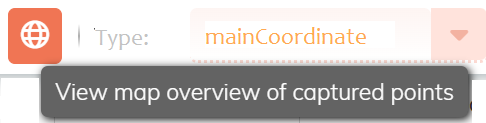
-
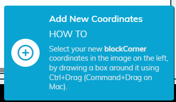
Type: BlockCorner - under Block Corners Heading in image
- From the Type dropdown, click on BlockCorner,
and click on the + icon to add new coordinates. -
- Once you have captured all the block corners, (it might need to be done in several passes if there is a large number to capture) and verified that the data in the grid matches the image, save your Project.
- From the Type dropdown, click on BlockCorner,
-
Type: SurveyMarks - under Town Survey Marks Heading in image
- From the Type dropdown, click on SurveyMark
and click on the + icon to add new coordinates. -
- Capture the Town Survey Marks as for the previous coordinates and verify that the data in the grid matches the image.
- From the Type dropdown, click on SurveyMark
-
- You can click on the globe map icon to see where the captured points have been placed:
-

- Once verified, save your Project.
-
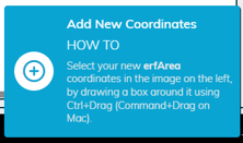
Type: ErfArea - Found under AREA (erf numbers, Squ metres) headings in image
- From the Type dropdown, click on erfArea and click on the + icon to add new coordinates.
-
- Capture the erfAreas as for the previous coordinates and verify that the data in the grid matches the image.
- Now that the points, coordinates, and distances have been captured we move on to pulling in the visual drawings of the maps so they can be GeoReferenced with this data. For each map we will link the coordinates to at least 3 points which will then be used to rotate and georeference the image s backdrop.
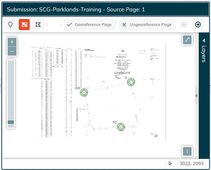
- Click on GeoReferencing (the 2nd button) to start processing the page selected under Project Submissions:

- You can then collapse the Project Submissions panel to maximise the size of the map image.
- The cursor now shows as crosshairs.

- Position it over any named point towards the top left of the image and left click: A textbox appears, and you need to enter the name of the point you selected, W in this example, then click on OK. Enter a minimum of 2 more points, one on the right and one at the bottom of the image, near the centre, so they form an evenly spaced triangle.
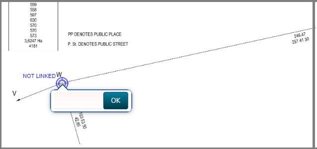
If you want to remove a point and choose a different one, hold down Ctl-key and click on the point to remove. Once you have chosen the points it is important to save them by clicking on
the Georeference Page button above the image to save your work.

-
Crop a Georeferenced Page:
blah-blah( How does one get to this crop a Georeferenced page?) Can we add the Clip icon ?
once you are happy with the crop lines, click on Clip Page at the top of the image panel.
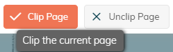
If you wish to redo the cropping, click on the Unclip Page button, and go back to crop again.
Once you have completed the first page move on the next page and repeat the process for each page in the PDF. You can advance to the next page by clicking on the Next Page button:

or, if you expand the Project Submissions panel on the left, you can click on the next page listed:
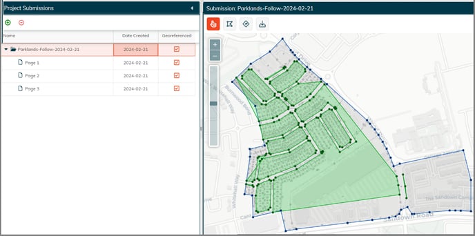
As each page is georeferenced the system ticks the box next to it. Proceed until you have processed every page.
Now go back to the first image in your pages (the folder entry). This is the combination of all the clipped pages below it.
Modify the Blocks
Now we will tidy up the clipped figures by grabbing and aligning the points of the 3 images (seen as green (street blocks), blue (main figure) and grey overlays). To do this click on the "Modify Blocks" button:
![]()
Click anywhere on a green line and drag it to correspond with a main figure coordinate (blue). It will snap to the closest one, release the mouse and click on the next part of the line you want to snap into place. Avoid moving the line parallel to an existing green line as this will reduce its ability to snap to a point.
Watch this video to see an example.
Once you have completed modifying the blocks, don't forget to SAVE your work.

Notes: when you need to pan the map, make sure you don't click inside the green area as you may inadvertently put down a point in the wrong place (and there isn't an undo button for this at present...?)
(Is there any way to remove a snapped point to redo it?
Can you move a snapped point?)
Create Erf Corners using Distance and Direction

Now start the process of using the captured distance and direction information and moving clockwise around each block to establish the outer boundaries of each erf.
Watch this video to follow an example.
Text explanation to follow.
Creating Inner Erf Lines
Once you have a block where all the outer boundary lines are filled in (brown), you are ready to fill in the inner lines. Part of this process is automated and is demonstrated in the video below. Some odd-angled lines may need to be filled in manually first before running the automated process.
To do this, make sure you have clicked on the erf lines button:
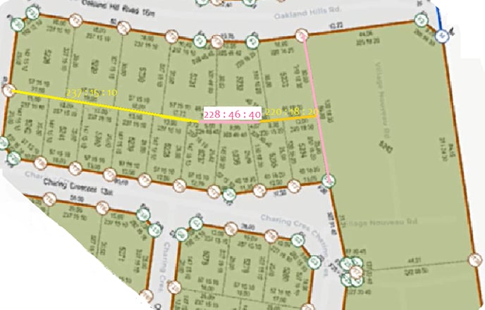
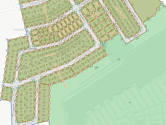
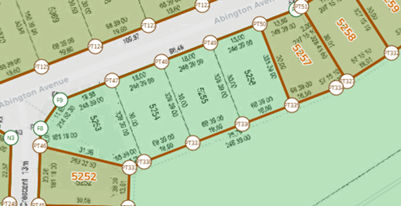
Consider this example:
The centre boundary lines between erven 5228-5233 and 5234-5242 change direction slightly at 3 points,
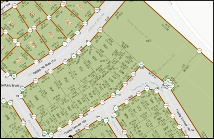
so we need to enter these manually. The image below highlights the three line segments to be captured, as well as the line at the end of thot block of erven (pink).
If an inner line segment you are wanting to capture runs parallel to an exist line on the boundary of that block, you can use the shortcuts: Alt-G to copy the direction of that existing LINE and then Alt-R on first POINT on the inner line you are updating. This will replace it's distance and direction information.
Automated Inner lines process:
click on any LINE as a starting point:
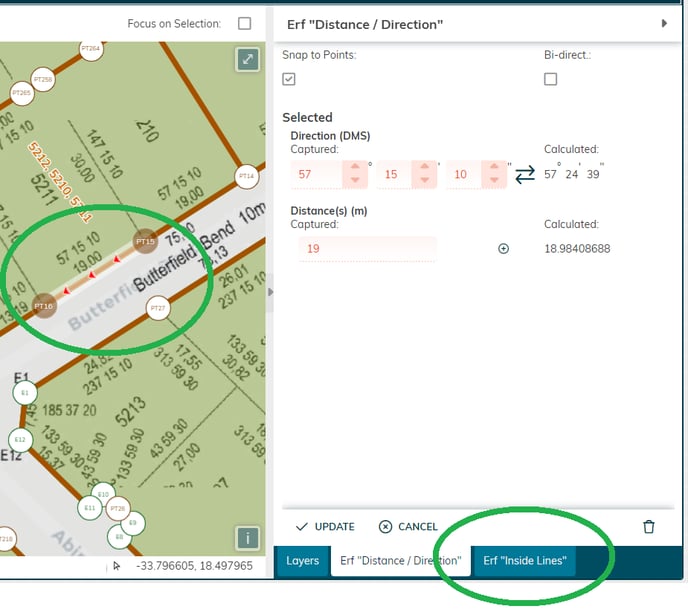
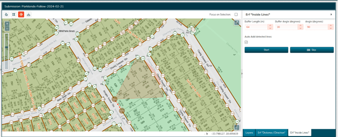
At the bottom of the "Erf Distance/Direction" panel, a new tab appears; Erf "Inside Lines".
Click on Erf "Inside Lines" tab. A "Pizza slice" appears highlighting the potential points that your initial point could be connected to.
Click on the blue Start button.
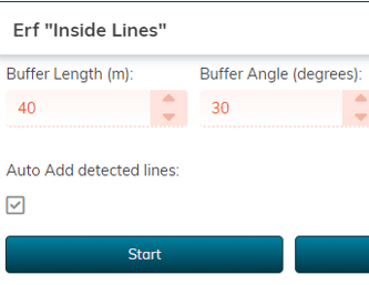
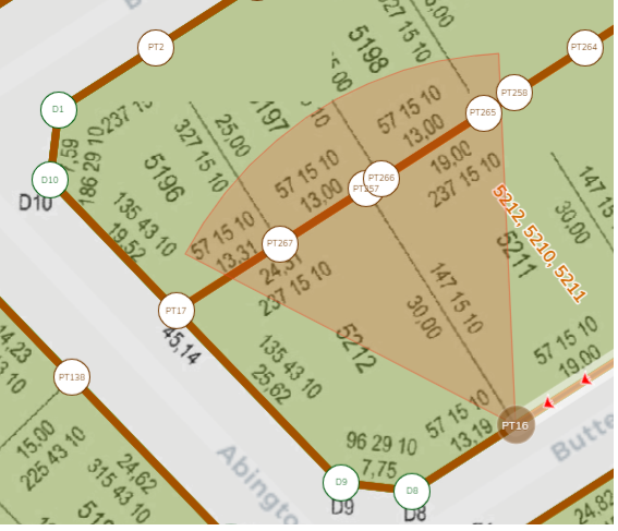
If the "Start" button is greyed out at the point where you have selected a line and the Pizza-slice has appeared on the screen, check if the area covered by the triangle is too small to reach a point opposite your starting point. If so, increase the Buffer Length (m). once it reaches the proposed point, the Start button will turn blue for you to click on it.
In this example, the initial point chosen was PT16, and the point that aligns with the property boundary (and is within the highlighted triangle) is PT257.
Once you click the start button the system automatically chooses the end point for each inner line throughout your chosen block.
Accurate matches turn the erf a brown shade, while those outside of acceptable tolerances remain green. These are the ones you need to manually update.
Example using this block:
watch this video:
In this example, we hadn’t done any of the inner lines to create smaller blocks, so the Automatic process just confirmed the outer borders.
Now let’s choose line near the middle of a border, which has a straight line to a point opposite, AND increase the buffer so the pizza-slice recognises the opposite point, and click start.
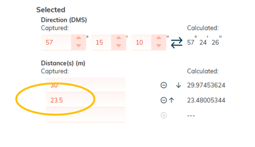
Once in motion, if the automation finds a line it cannot resolve, it will display the line with red dots and await your intervention. In this case P170 to F14 should only have one 30m segment, and the second stops 6.5m short. Reduce the 2nd entry to 23.5 m.
Once all lines which are not connected to a border line have been added manually, rstart the automated inner line process by clicking one of the border lines
If there are any erven that are still green, check and update manually.
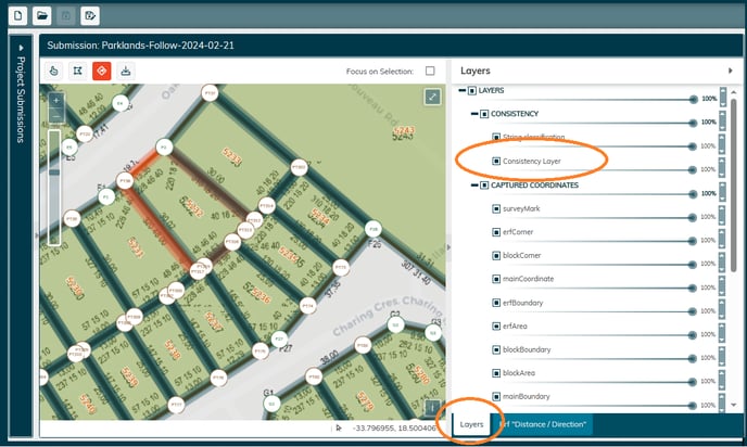
Consistency Checks using Layers
Click on the "Layers" tab (bottom right)
Click on the radio button next to Consistency layers to have them displayed over your map image. Consistent lines are overlayed in blue. In this example, erf 5232 is overlayed in red, indicating that discrepancies have been detected. Check each line for distance, direction, whether a point is missing, whether a bidirectional line has only been captured in one direction, etc.
Export Data and Shape Files